Details to Hollow-Fibre-Filter modules
Cross-Flow-Filter (CFF) expression covers a range of systems and technologies. The Hollow-Fiber-Filter (HFF) membrane module or cartridge - is a device that can serve to transfer selected gases, liquids, particles between two fluids. In the pharma industry a HFF device is designed with an outer rigid wall tube equipped with tube housing end covers. Inside the HFF cartridge a bundle of thin wall circular straws, lumen fabricated from porous polymeric material such as PolyEtherSulfone PES or PolySulfone PS. This bundle of straws is sealed, cast into end covers separating the straw inside surface from the straw outside surface. The HFF for perfusion purposes has technically a first broth inlet, a second retentate outlet and two third permeate outlets.
HFF modules was originally developed for the dialysis industry after WWII and surprisingly the principal design have not changed. The two permeate outlet are not designed as permeate outlet for the mammalian cell culture perfusion industry but for blood cleaning purposes. Current HFF for perfusion are based on a stack of straws, lumen with inner diameters (ID) 1 mm. Lately also available in 2 and even 3 mm diameter for biotech purposes.
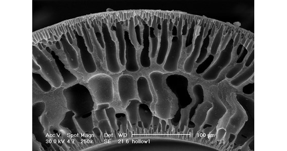
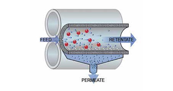
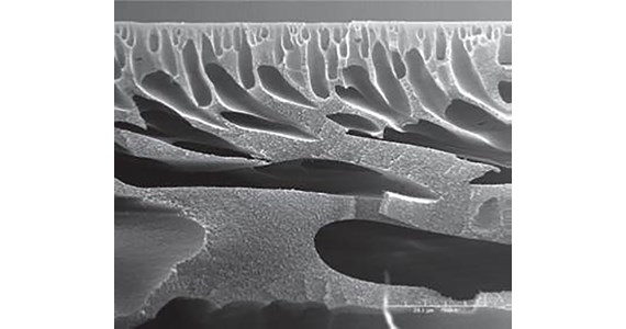
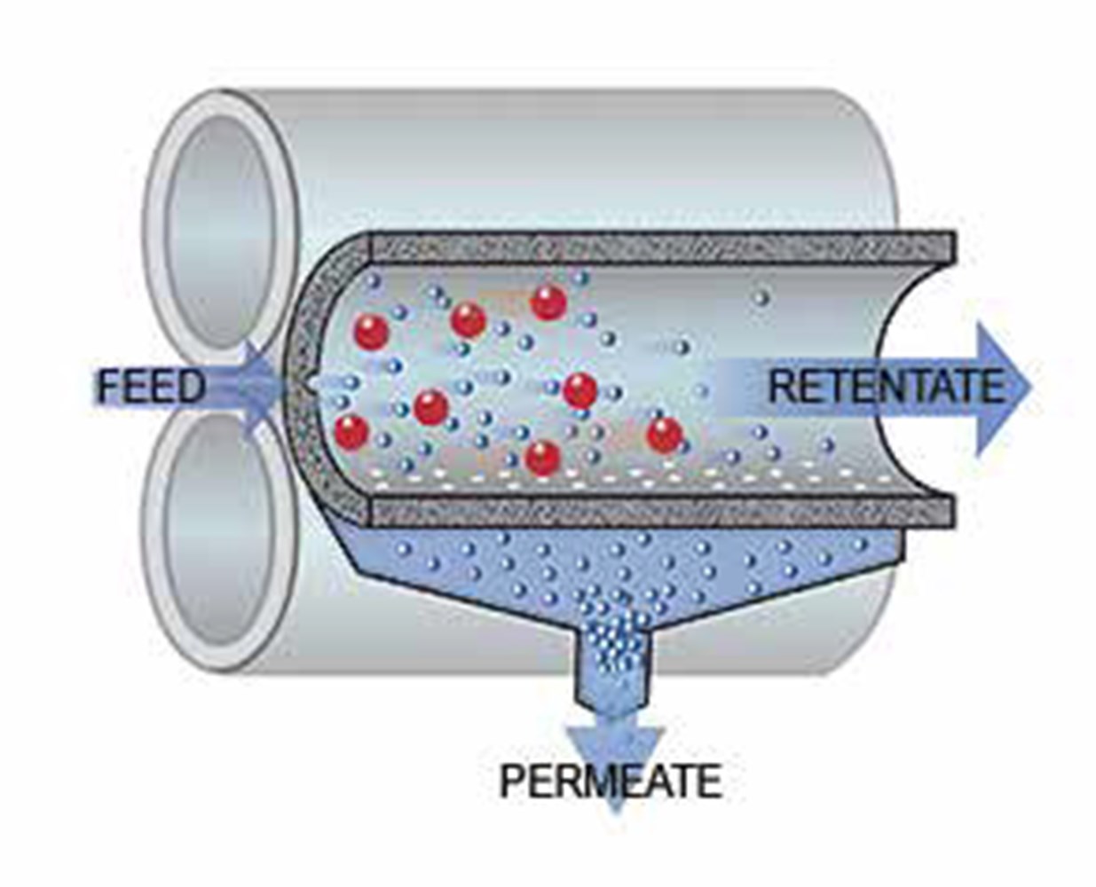
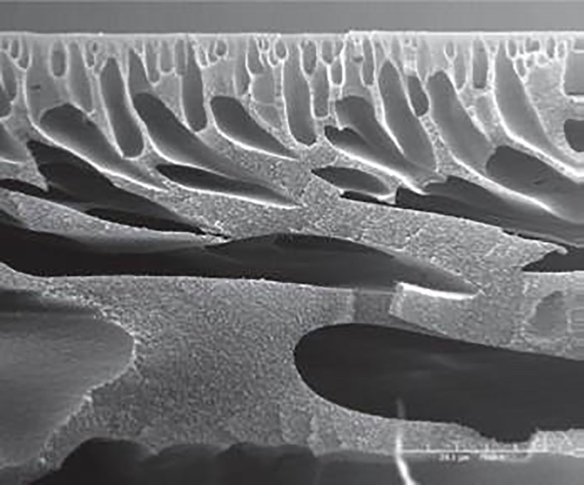
SEM photo of a 0.4 mm straw wall section Polyethersulfone (PES). Illustration of Hollow-Fiber-Filter (HFF) principle with 3 bundled straws - red particles = CHO cells, blue particles = proteins passing the cylindrical membrane wall, barrier. SEM photo of MPES membrane from old SpectrumLabs.
Important measures
TMP - (Trans-Membrane-Pressure) is the difference between the average upstream, feedstock inlet pressure and permeate pressure after the Cross-Flow-Filter membrane. The pressure difference across the filter membrane = TMP is the driving force for membrane flux = harvest. TMP will increase between Cleaning Cycles as a function of the severe fouling increase.
TMP is the net pressure that forces the part of the broth to become permeate through the membrane and is typically calculated as the average of the inlet and outlet pressures minus the permeate pressure. The equation is generally expressed as:
TMP = (P_in + P_out) / 2 ÷ P permeate
Several factors influence both TMP and pressure drop, impacting how they interrelate. In membrane filtration, membrane fouling is a significant factor that increases TMP over time. Fouling occurs when particles, colloidal materials, or biological substances accumulate on the membrane surface, increasing resistance to flow. This can lead to a higher TMP as more pressure is required to achieve the same harvest flow rate.
TMP refers to Trans-Membrane-Pressure. TMP is the driving pressure difference that moves liquid and low molecular weight solute through the membrane. When controlling a filtration process with TMP control, pressure is regulated, controlled at both the feedstock inlet and retentate exit port, and flux (flow through the membrane) is governed by porosity, pore size, surface area, broth viscosity, solute concentration, concentration polarization and pressure. In this mode, flux is high at the beginning of the process, but diminishes as a function of time/throughput as to membrane fouling. This fouling is what Clotho / Thalia / Clio is able to remove via the Cleaning Cycles.
DeltaP / ∆P – (Pressure-Drop) is the difference in pressure between two points in a flow system. It reflects the resistance the fluid encounters as it moves through a filter or a series of lumens in parallel. The greater the resistance, the larger the Pressure Drop, which are caused by factors such as the length of the lumen, its diameter, the roughness of its interior surface, possible increased fouling and the viscosity of the fluid.
The pressure increase is the difference between the HFF feedstock, broth inlet port and the retentate exit port. Low, close to atmospheric pressure in the broth volume of the SUB. High at the retentate outlet as function of HFF fouling. DeltaP ∆P will increase as a function of the ID of the lumen decreases as to unavoidable fouling. Pressure Drop are affected by the characteristics of the fluid being processed, such as its viscosity and temperature. A higher viscosity fluid, such as containing high biomass levels, will naturally result in a greater pressure drop, as will lower temperatures that increase fluid density and resistance to flow.
The drive units Clotho, Lachesis, Atropos measures DeltaP ∆P continuously.