
Tips & Tricks
The most commonly used separation / cell retention membrane / Cross-Flow-Filter (CFF) devices used in pharma upstream for semi-continuous perfusion for expression of mAbs is known as Hollow-Fiber-Filter (HFF).
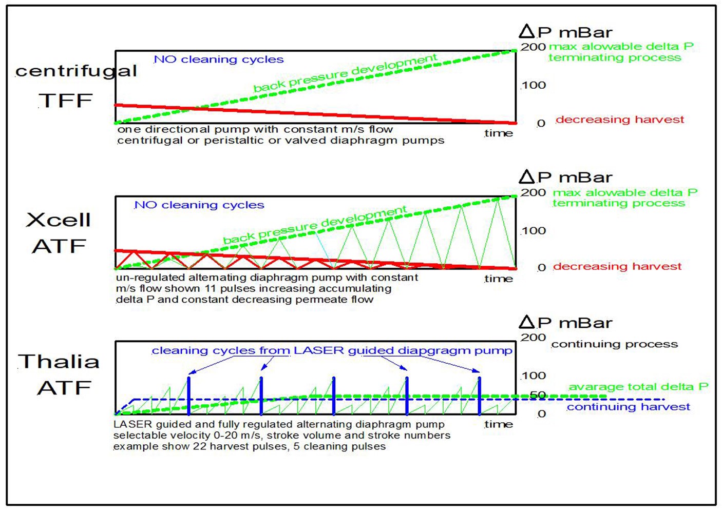
This simple chart illustrates differences in HFF conditions seen from pressure drop against fouling according to the chosen pump principle.

In the industrial filtration, particle separation industry, its well-known that a clean filter with preferably low pressure drop is based on sequential cleaning, removal of collected particles, fouling which is collected, seperated from the fluid passing through the porous wall.
Cleaning sequence, intervals differs based on many parameters:
- Filter physical size and shape, mechanical stability, possible extra mechanical support
- Materials such ceramic, metal, polymers, fabric – rigid or elastic
- Porous wall filter designed as one or many cylinders (lumen), a multi-channel honeycomb, flat surface
- Rigid non elastic wall structure without the need of mechanical support
- Elastic, flexible porous wall with or without mechanical support
Cleaning sequence depending on:
- Particle properties, fluid temperature, viscosity
- if rigid porous wall
- if elastic porous wall
- is flexible porous wall but not elastic
The particular fluid being processes is most often the source for fouling, cake and also for removal of the filter fouling, cake on the collection side:
- Back flush – fluid velocity increase as a short pulse in opposite direction to the process fluid direction, such pulse during filter operation releases the filter cake from the membrane and removed, flushed out by the process fluid
- Front flush – short significant fluid velocity increase, like a pulse along the collection membrane releasing the filter fouling, cake and removed, flushed out by the process fluid